Integrating Roller Conveyors With Work Positioners: Material Flow Design

Key Takeaways
- The manual transfer between conveyor and workstation is where cycle time, injury exposure, and quality variation concentrate. It is also the cheapest place to fix all three.
- Matched heights are the foundation of an integrated handoff. If the part has to be lifted over anything, the design is not finished.
- Reorientation is the hidden manual step. Multi-directional rollers turn the part at the transfer point so nobody has to.
- Size the positioner by weight, number of faces to reach, and how often the setup repeats, from a 300-pound manual unit up to 17,600 pounds under program control.
- Sensors, stops, interlocks, and guarding are part of the design, not an afterthought. A transfer point creates nip points and rotating hazards by definition.
- Justify the project on recovered cycle time, avoided claim cost, and reduced rework, using numbers you can measure on your own floor.
When a production line stalls, the conveyor usually gets the blame. More often the loss sits in the few feet between the end of the conveyor and the work surface, where an operator lifts a part off the rollers, turns with it, sets it down, and then fights to hold it at a workable angle.
Integrating a roller conveyor with a work positioner closes that gap. The part leaves the conveyor at the same height it lands on the positioner, gets secured, and is presented at the angle the task actually requires. No lift, no twist, no second set of hands.
Good work positioner integration comes down to four decisions: which conveyor delivers the part, which positioner holds it, how the transfer between them is controlled, and how the whole cell is guarded. This guide covers all four, and the material flow design principles that keep the handoff safe and repeatable shift after shift.
Why the transfer point costs more than the conveyor
A manual transfer between a conveyor and a workstation looks minor on a process map and expensive on the P&L. It costs cycle time, it creates injury exposure, and it puts variation into work that depends on consistency.
Start with time. Every transfer stops the cycle. The operator sets down a tool, squares up to the load, lifts, pivots, places, and re-grips. Ten to twenty seconds per part is common, and on a line running several hundred parts a shift, that becomes hours of paid time spent moving material instead of building product.
Next is the injury exposure. Manual handling of heavy or awkward parts is one of the most reliable ways to generate musculoskeletal disorders in a plant, and the transfer point concentrates the worst risk factors in a single spot: the load held away from the body, a twist while loaded, and high repetition. Those claims hit the same budget that would have paid for the equipment.
Quality is the cost that gets missed. When an operator places a part on a static fixture by hand, the height and orientation shift a little every cycle. For welding, sealant and adhesive application, torque work, or inspection, that variation shows up later as rework and scrap.
What a well designed handoff looks like
A good transfer is one the operator does not have to lift, plan, or correct. Four design decisions get you there.
- Matched heights. Top of roller sits level with the positioner’s receiving surface at its lowest setting, so the part slides across rather than being lifted over.
- A controlled stop. A mechanical stop, pneumatic gate, or photo eye holds the part in the same place every cycle, so the transfer always starts from a known position.
- The load secured before anything moves. Fixturing or clamps hold the part, and the control logic keeps the positioner from tilting or rotating until it is locked.
- Presentation, not just delivery. Delivery gets the part to the operator. Presentation puts it at the working height and angle for the job, which is where the cycle time and ergonomic gains actually come from.
Step 1: Match the conveyor to the part
The conveyor decides how the part arrives, and that sets the terms for everything downstream.
Gravity roller conveyors are the simplest and cheapest option, and they work well for flat-bottomed parts moving short distances into a manual workstation. The operator controls the timing, which suits variable cycle times and mixed-model work.
Powered roller conveyors make sense for heavier parts, longer runs, and any cell where the part has to arrive at a set time and a set place. They also let you slow the approach into the transfer point, which matters when the part is heavy enough to shift on impact.
Belt conveyors move small parts and unstable shapes well, but the belt surface makes the slide-across transfer harder. For direct integration with a positioner, rollers are usually the better choice.
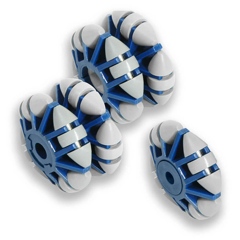
Direction is the constraint most layouts underestimate. A straight conveyor delivers the part in one orientation. If the positioner needs it turned 90 degrees, someone turns it by hand, and you have designed a manual lift back into an automated line. This is where multi-directional conveyor rollers earn their keep. The Ergo Roll® mounts four football-shaped rollers in a staggered pattern around a main hub, giving five rotational axes per wheel and nine in a side-by-side duplex module, so a part can be turned or moved sideways where it sits. Each roller carries 12.5 to 90 pounds, fits most common conveyor axle configurations, and installs into new or existing gravity and powered conveyors. The non-marring self-lubricating plastic will not scratch a finished surface and needs no lubrication, wet or dry.
If you are specifying a new line, size a heavy duty roller conveyor around your heaviest and most awkward part, not the average one. If you are fixing one problem station in an existing layout, a short transfer section built from multi-directional rollers is usually the faster and cheaper change.
Before you specify anything, get answers to these:
- Weight and footprint of the part in its heaviest configuration
- Whether the base is flat and stable enough to slide without tipping
- Required throughput, in parts per hour at the transfer point
- Whether the part has to be reoriented before work can start
- Coolant, chips, wash-down, or dust in the area
Step 2: Size the positioner to the task
Choose the positioner by three things: the weight of the part, how many faces the operator needs to reach, and how often the setup changes. Ergotronix publishes four work positioner lines, all made in the USA.
| Line | Control | Published load capacity | Where it fits at a transfer point |
|---|---|---|---|
| Ergo Master | Manual | 50, 150, 300 lb | Operator pulls the part off a gravity conveyor and repositions by hand |
| Ergo Chief | Motorized | 400 lb | Powered rotation and tilt at a manual or semi-automated cell |
| Ergo Force | Motorized | 600 and 1,500 lb | Heavier parts, and any job that needs the part turned past vertical |
| Ergo Control | Programmable | 660 to 17,600 lb | Repeat production where positions need to be sequenced and stored |
For light, low-volume work, a manual unit is often enough. The Ergo Master handles up to 300 pounds with adjustable friction through the positioning stroke and a holding lock at the chosen position, so the operator is not bracing the load with their own strength.
Once parts pass a few hundred pounds or the cycle repeats all shift, powered positioning pays for itself in fatigue alone. The Ergo Chief carries up to 400 pounds with variable-speed bi-directional rotation, up to 90 degrees of tilt, and hand pendant or foot pedal control. Its turntable has eight concentric radial channels, which makes it straightforward to bolt down a fixture that matches the way the part comes off the conveyor.
For parts up to 1,500 pounds, or work that requires access to the underside, the Ergo Force uses an L-shaped arm with unlimited turn and tilt, so the part can be rotated upside down instead of unloaded, flipped, and re-fixtured. On an integrated line that removes an entire handling step.
At the top of the range, the Ergo Control covers 660 to 17,600 pounds with teach programming and stored position sequences, plus a built-in 400A rotary ground for welding. In a cell where the same three or four positions repeat on every part, a stored sequence removes the guesswork between operators and between shifts.
The full work positioner comparison lays out capacities, tilt, and control options side by side. If you are still weighing a motorized and manual work positioner against each other, the decision usually comes down to part weight and how many times per shift the operator repositions the load.
Step 3: Control the transfer and guard the moving parts
An integrated transfer needs four things: a sensor that knows the part has arrived, a stop that holds it in place, an interlock so the positioner cannot move until the load is secure, and guarding wherever a hand can get caught.
- Photo eyes confirm the part has reached the transfer position and signal the positioner to be ready.
- Mechanical stops or pneumatic gates hold the part square to the positioner instead of relying on the operator to line it up.
- Interlocks keep the positioner from tilting or rotating until fixturing is engaged, and keep the conveyor from releasing the next part until the station is clear.
- Fixed guarding covers the pinch points created where the conveyor and positioner meet, which is the hazard people add and then forget.
- Emergency stops within reach of the operator on both the conveyor and the positioner.
- Light curtains or area scanners where the cell runs powered motion with the operator close by.
OSHA’s general machine guarding requirement, 29 CFR 1910.212, calls for guarding that protects operators from points of operation, ingoing nip points, and rotating parts. A conveyor-to-positioner transfer creates all three, so treat guarding as part of the design rather than something to add after the cell is running. Our guide to OSHA compliance in manufacturing covers the standards that apply most often to material handling cells.
How the two machines talk to each other depends on how much sequencing you need. Relay logic handles a simple stop-and-release. A PLC makes sense once you are coordinating multiple stops, stored positioner sequences, and upstream or downstream equipment.
A shop floor example: manifold sub-assembly
Here is what the change looks like on a specific station. The numbers below are representative of this type of job rather than a customer case study.
Before. A powered roller conveyor delivers 40-pound engine manifolds to an assembly station. The operator lifts each manifold off the conveyor, carries it a step, sets it on a static fixture, then leans over the part to reach the fastener locations on two faces. The lift and the sustained forward lean are the two ergonomic risk factors, and both repeat several hundred times a shift.
After. The static fixture is replaced with a motorized positioner set to the same height as the conveyor.
- The manifold travels down the conveyor and stops against a pneumatic gate directly beside the positioner.
- The operator slides it across from the rollers onto the fixture and engages the clamps.
- A pendant press rotates and tilts the part to the first work position, at standing height.
- A second press moves it to the next face. The operator never lifts the part or leans over it.
The lift is gone, the forward lean is gone, and the two seconds spent hunting for a comfortable angle on each face is gone. That last one sounds trivial until you multiply it by the shift count.
What the handoff is worth
The business case is arithmetic, and it is usually stronger than people expect before they run it.
Recovered cycle time. Save 15 seconds per part on a line producing 1,000 units a day and you recover just over four hours of labor time daily. That is the single easiest number to defend, because you can time the current transfer with a stopwatch this week.
Avoided injury cost. One back or shoulder claim carries direct medical and indemnity cost plus the indirect cost of overtime, retraining, and restricted duty. In many plants a single avoided claim covers the equipment. This is the number the safety and operations budgets should be looking at together.
Lower rework. Consistent part presentation means consistent weld position, consistent torque access, and consistent inspection angle. Fewer defects per thousand is real money in any operation with a scrap line item.
Good ergonomics equals good economics, and the transfer point is where both are usually being lost at the same time. If you need to put the case in front of a CFO, our framework for calculating return on investment on ergonomic lift equipment walks through the inputs line by line.
Retrofitting a line that is already running
Most integration work happens on existing lines, not clean-sheet layouts. Three variables decide how hard it will be.
Height. Either the conveyor section gets adjusted or the positioner installation does. Verify the conveyor’s top-of-roller height and the positioner’s lowest receiving height before anything is ordered, not after.
Floor space. A positioner needs an operator envelope around it and clearance for the tilt and rotation path. Measure the swing of the part, not just the footprint of the machine.
Controls and safety. Adding sensors, interlocks, and guarding to a running line takes coordination with maintenance and whoever owns the line’s control system.
The sequencing matters as much as the hardware. Phasing the work so you can install and commission without disrupting production is usually the difference between a project that gets approved and one that stalls. Send the part drawings and the conveyor dimensions to an applications engineer early, because the answer to “will this work” is almost always in the geometry.
Design the handoff before you buy the equipment
Most integration problems come down to geometry that was never checked: a conveyor two inches too high, a part that needs turning, a tilt path that hits a column. Ergotronix engineers positioners to order for the parts they will actually handle, and that starts with your drawings and dimensions.
Send us the part, the conveyor, and the task, and we will tell you what the transfer point should look like. Request a quote and start making your factory safer.